Solar Airplane

Project Overview

The UCI Solar Airplane project aims to demonstrate the viability of solar panels for increasing the flight duration of unmanned aerial vehicles (UAV) and to create a vehicle capable of assisting in search and rescue missions for natural disasters.

Design Requirements

  • Must be functional
  • Must be powered by solar panels and batteries
  • Must have a flight duration extended by 30 minutes beyond the battery life in sunny weather conditions
  • Electronics and Propulsion equipment must be integrated and easily accessible throughout the aircraft
  • Must fit in a standard truck bed (6.5ft x 4.2ft)
  • GPS and camera must be integrated with acceptable video quality
  • In-flight data must be given via remote terminal

Visit the project website!

Year Selection


CAD Design

Rib Design

I was tasked with creating CAD models for ribs that form the main aerodynamic structure of the wings.

Part Requirements

  • Must range in chord length as the wing tapers
  • Must have aligned circular spar hole cutouts corresponding to off-the-shelf carbon fiber rods perpendicular to the fuselage.
  • Must have additional cutouts for mass reduction and wire routing opportunties
  • Must have cutouts for skin features, such as sheeting on the leading and trailing edges or stringers.
  • Must be formed from laser-cut balsa wood sheeting

In an ideal case, the ribs would also be very easy to modify, so having 30 separate part files like in the previous year (yikes) is out of the question. I needed to find a solution to have numerous ribs, placed at arbitrary span distances along the wing with perfectly positioned spar holes to ensure appropriate wing geometry, and with other more complex features.

The Rib Former

Using Solidworks CAD, I developed a uniuqe solution for creating easy-to-modify tapered wing ribs which could be manufactured from flat sheets on a laser cutter.
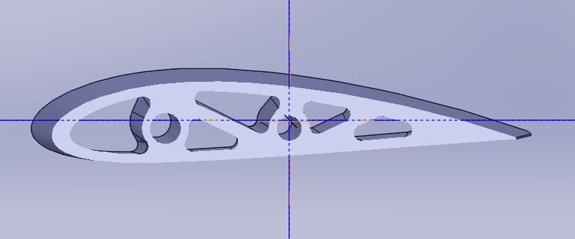
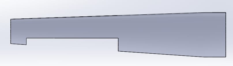
Cross-section of the solar airplane rib former Full CAD rib former for the solar airplane wing

What I call my rib-former method involved a single part file with multiple configurations representing each rib the wing requires. The single part file starts with a loft between a start and end airfoil profile, creating the root and tip of the wing. This solid block then has multiple lofted cuts taken out of it to provide cavities for wire routing and spar placement. Additional lofted cuts can be made for other geometry, like the stringer and sheeting cutouts (not pictured above).

The result is a solid block with tunnels representing where objects (wires and spars) can go through the wing, and external parts may be added (stringers and sheeting). In other words, this is the sum of infinitely many, infinitely thin ribs that could exist along the wing. The next step is to create a sketch that takes the intersection geometry of the former block with a plane perpendicular to the span of the wing, and at the desired span distance. Then, that sketch geometry is extruded to the thickness of the rib stock material (1/8in), ready to be placed on the assembly or saved as a dxf for cutting. Using an excel design table, I can easily create a new configuration of the part to form a rib at any arbitrary distance from the root that I desire, without having to modify anything else.

Results

This method of creating ribs saved a lot of time during development, and made changes of any magnitude very simple to conduct. For example, rather than having to modify the spar diameter on two dozen part files separately, I just had to modify three sketches, and it updated every part. When we were still figuring out the ideal rib spacing, I could easily decide to put a rib at any position along the wing with a simple update of the excel design table, and it was done. This made modificaitons to the layout incredibly simple. I was surprised that in my research I did not find anyone else using this method, instead going for the tedious part-by-part method.

One of the greatest disadvantages to my design is the computational power required, and lag induced, by the parts. Because every part rebuilds by calculating every feature of the wing, even those not near the rib, and because those features (lofts) are more complicated than traditional features (straight extrudes), rebuilding the assembly was very slow.

Ultimately, the team decided to go with a rectangular wing (no taper) and I reverted to a more simple part with a handful of configurations to, for example, remove the trailing edge to make room for the aileron. I was disappointed that my hard work developing the former was not going to be used in the final product, but understand that the manufacturing benefits of a rectangular wing outweighed the performance gain from a taper.
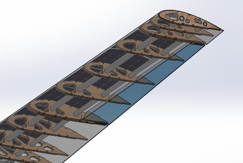
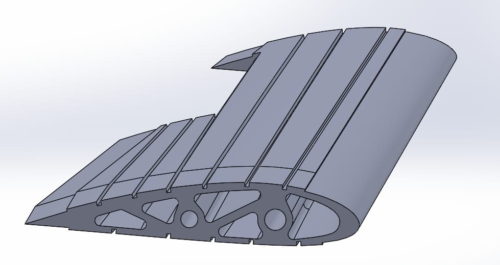
Underside of the tapered solar airplane wing Grooves and tunnels in the solar airplane rib former

Manufacturing

Laser Cutting

I utilized UC Irvine's FabWorks 70W laser cutter to create the ribs out of 1/8" balsa wood. I started with a test cut to ensure a proper fit with the spar and that the laser would cut properly. After adjusting the spar hole diameter to create an acceptable fit, I cut out around 80 ribs for the wings.

Glue Up

Adhesive Choice

As a new member, I was introduced to the previously used methods of adhering the ribs to the spars: 5 minute epoxy resin. I was absolutely horified by the prospect of working a few ribs at a time, constantly pouring new batches of carcinogenic fumes and safety hazards, and taking a long time with each rib. So, I proposed using the super glue we had on hand. I wasn't sure if the super glue would be strong enough for our needs, or if it would even bond well to the wood and carbon fiber tube. So, I made a test glue up with old scrap parts, and determined that, at least within a few days of applying, the super glue bond was stronger than the wood. This meant that we could proceed with super gluing the ribs on, which significantly reduces the hazard we are being exposed to (and ppe required), and speeds up the process of attaching ribs to the spars manually.

Isn't Super Glue Brittle?

I also weighed other factors, such as the ductility of the bond and the long-term expected performance of the adheasive. The wing ribs are connected at four main surfaces: The two spars via an adheasive, and the top and bottom surfaces of the wing via wood stringers and heat-shrunk plastic. Considering that the majority of the loading on the wing is radial from the axis of the spars, I determined that the ribs would be unlikely to experience significant axial loads (along the spar) or twisting moments (perpendicular to the spar) that would cause slight deformation at the spar glue joint. Because the joint isn't expected to experience loads along to the glue surface, a failure of this joint would probably not lead to significant consequencs for the aircraft, so I was comfortable using a more brittle super glue instead of epoxy resin.

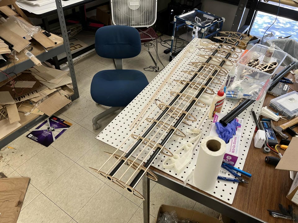
Solar airplane wing during rib assembly

Gluing on the Ribs

Using 3d printed jigs to ensure the spars were parallel and the ribs were perpendicular to both spars while gluing, I meticulously followed my prepared solidworks assembly drawings with measurements for the placement of each rib. Because the wings had to be divided into 3 sections - the two sides removable for easy transport - I used internal ferrules epoxied within the outer spars that nest within the inner with a friction fit. The ferrules were designed with a very small clearance between them and the spars, so the distance between the spars on the removable section had to be exactly the same as that on the inner sections. To ensure a proper fit, I actually inserted the spars into each other before gluing the ribs on to one half, that way the spars would be guarunteed to fit.

This method proved to be very effective at ensuring the segments fit together, although I forgot to use it on the 2025-2026 aircraft and alignment issues required the ferrule to be carefully sanded down to allow for a flush fit between the sections.

Fuselage Help

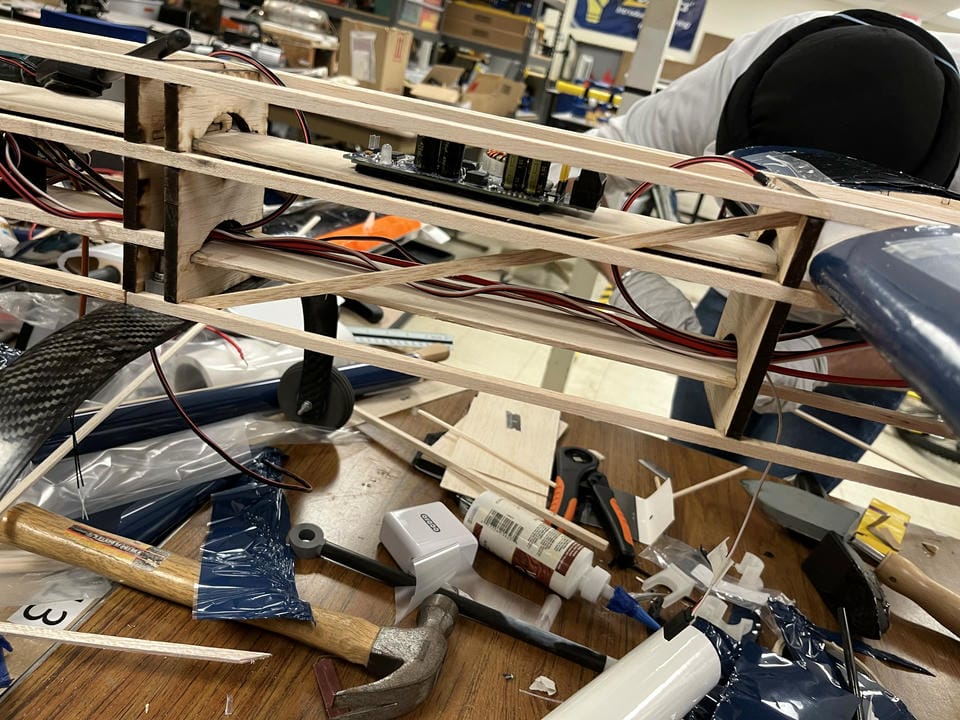
Diagonal bracing added inside the solar airplane fuselage

I assisted the fuselage subteam with manufacturing the fuselage, and identified multiple points where the structure was not rigid enough to fly properly due to design oversights. I attempted to remedy this by installing diagonal trusses in the structure, and later by placing wood sheeting along the entire side of the fuselage at the advice of a mentor. Unfortunately, this did not resolve the issue, and we ended up flying with a twisty fuselage, which was quite annoying considering the tandem wing configuration, which flew cockeyed, with the wings not being parallel to each other.

Flight Day

Test Flight One

After many delays to the project, I was very excited to finally fly the plane after over a year of working on it. Unfortunately, we ran into a few issues...

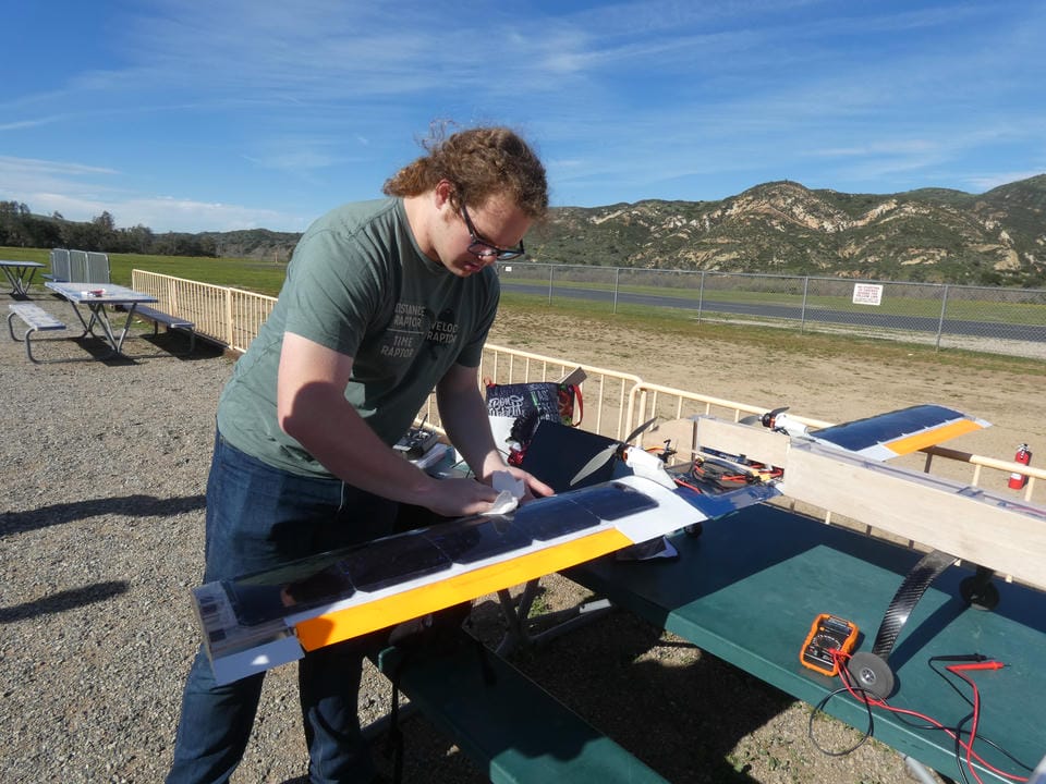
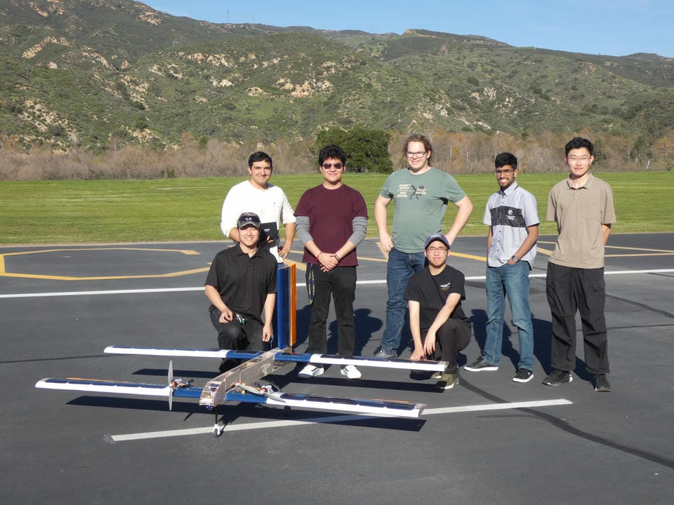
Team member cleaning the solar airplane panels Solar airplane team beside the tandem-wing aircraft
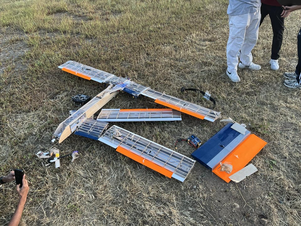
Solar airplane after an unsuccessful flight attempt

It Broke.

The first flight attempt didn't manage to get off the ground because, in short, the center of gravity (CG) was too far forward relative to the rear landing gear.

To explain how we got to that point, it's important to take a look at the development leading up to the flight. The Fuselage and Aerodynamics subteams largely worked independently, with general meetings each week to catch up. However, due to poor communication between the subteams, and a lack of sufficient aerodynamic analysis pre-fabrication, the fuselage ended up being constructed with the rear landing gear in an arbitrary location.

How to get off the Ground

In order for an aircraft to get off the runway, the lift force must exceed the weight of the aircraft. Because our vehicle does not have flaps, that means that the angle of attack (AOA) of the aircraft must be somewhere around 5 degrees at our 20m/s top speed on the runway during that flight attempt. Typically, an aircraft is able to pitch up while still on the runway, easily achieving that required AOA while on the runway. Because our landing gear was too far back relative to the CG, the pitching moment of the weight of the aircraft about the wheels was significantly greater than the max pitching moment the elevators could induce. This meant that we were unable to pitch up on the runway, and therefore unable to take off.

Design Conflicts

But why not move the CG back? The neutral point (NP) is an imaginary point about which the pitching moment is constant with respect to angle of attack, and is used for static stability calcuations for aircraft. If the NP is behind the CG, the aircraft has a positive static margin, and is statically stable - that is, with no control inputs, it will fly fairly straight, as opposed to going into death spirals. In order to have sufficient static margin, the CG had to be moved a particular distance in front of the NP. And because the analysis to determine the NP location was done after manufacturing, it was too late to modify the aerodynamics and NP position. So, we were forced to move the CG to a specific spot along the aircraft, which happened to be far in front of the rear landing gear.

The Solution

After weighing multiple solutions, I determined that the best course of action to fly the plane was to extend the front landing gear such that the aircraft has the roughly 5 degree AOA while sitting on the runway, without needing to pitch up. This was the simplest solution for us to implemenmt, as the nose gear was already in need of replacement after the crash.

Fluid Simulations

Software Selection

In order to expand my skillset and develop a thorough understanding of what went wrong with the previous flight, I wanted to use computational fluid dynamics (CFD) to evaluate the aerodynamic characteristics of the aircraft.

I researched some CFD tools, and found that Solidworks has a flow simulation add-in included in my license (although the industry doesn't seem to favor it), and Ansys has a tool called Fluent which is much more utilzied in the industry, and is expected to give better results. Because Solidworks Flow Simulation would be easiest to integrate with our workflow, and is more user-friendly, I decided to start my simulations there.

Solidworks Flow Simulation

I ran a handful of simulations using Solidworks and a basic setup, recording lift and drag as a function of angle of attack, as well as the pitching moment. I analyzed the results and found the neutral point of the aircraft by calculating the slope of the pitching moment vs lift force near 0 degrees AOA. Because this was my first time using CFD, the results were likely not very accurate (due to user error), but I still wanted to give Fluent a try, and see how they compare.

Ansys Fluent

Right off the bat, I discovered that Ansys Fluent was going to be a lot more difficult to use than Solidworks. I found that finding the right tool to use was very difficult at times, and setting up anything was difficult. Importing the geometry and configuring motion of the control surfaces and the aircraft as a whole was very challenging. When I got to the meshing stage, I discovered after hours of failed attempts that Ansys offers two meshing tools. The default one in the workflow is not intended for fluid simulations, and caused a lot of problems. The other one, Fluent Meshing, worked much better. Despite this, it still took countless hours of failed meshing and random failures and software crashes to even get that completed. Once I figured out the meshing, it was fairly straightforward to set up and run the fluid simulation with design parameters for all of my desired variables (speed, AOA, etc).

In total, I ran over 20+ design point simulations to create a thorough picture of the aircraft's performance. Doing the same NP calculation as before, I found that the two softwares matched within about 10% of the mean-aerodynamic-chord (an important reference for static margin calculations). Although this isn't particularly promising, I will note that the solidworks simulations were not done particularly well, including a very small fluid domain and poor meshing. Because I ran multiple ansys simulations, some with different domains and meshing parameters, and found very similar results each time, I trust the ansys simulations to be more accurate.

CFD Video Tutorials

Because of the difficulty I faced while learning Fluent, I decided to help my teammates out by recording video tutorials for the whole Fluent process. This allowed them to run some basic simulations without having to spend the countless hours I did facing various errors, failures, and crashes.

Flight Day Two

After fixing the front landing gear, and checking calculations over again, I was confident that the aircraft could take off the runway and be stable in flight.

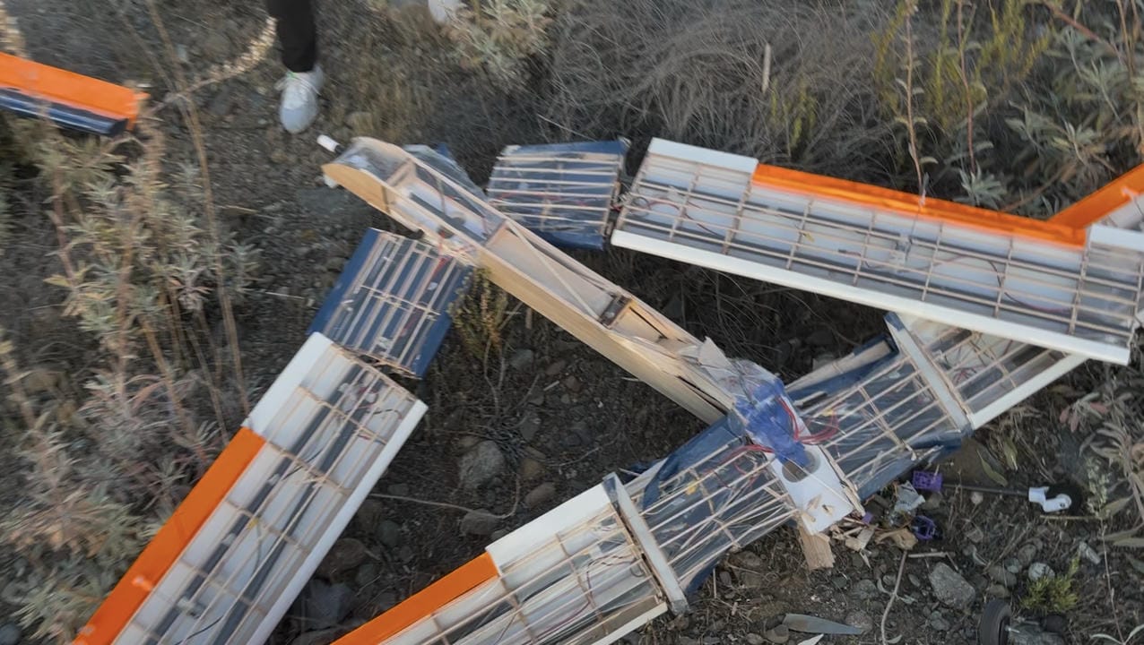
Wreckage of the solar airplane after the second flight Close view of the solar airplane crash damage

That Didn't Go So Well...

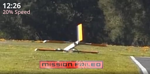
After about 30 seconds of flying very well, the aircraft took a sudden nose-dive into the ground. After analyzing onboard flight data and reviewing flight footage, we were unable to identify the exact cause of the failure.

Post-Crash Investigation

I led the crash investigation, doing most of the analysis on my own. I was able to rule out electrical failure, as the battery voltage and current readings did not show significant changes during the anomaly. Data indicates that the aircraft was in manual mode during the entire flight, meaning the pilot had direct control the entire time. The aircraft did recieve commands to pitch up, and executed them by moving the servos, as can be confirmed by the footage. Two minor anomalies can be seen in the attitude data and flight footage, where it appears that the aircraft started stalling for a brief period of time, rapidly decreasing in pitch for a moment. Despite this, the aircraft seemed to recover very quickly, and this behavior does explain the slow decrease in altitude preceding the nose dive.

We were unable to identify any significant changes in data immediately before the nose dive that could indicate a cause for such a sudden change in attitude. We also did not notice any mechanical failures in the flight footage, and we examined the control surfaces and their control horns for damage after the crash. Despite the crash, all control surfaces were still attached to their control horns and their servos.

Possible Explainations

One possibility is that the tape used to attach the control surfaces to the wings had flexed significantly, causing the wing contour to significantly deform, and the control surface to change orientation. While we have observed some small wiggle in the attachment point during pre-flight testing, we do not find this option very likely, as the tape is very sticky and unlikely to come undone enough to cause such a dramatic loss of control.

Another, more likely, possibility is that some internal components were not securely fixed in place, and had managed to shift during flight. If enough weight had moved, the plane could lose it's abiltiy to maintain attitude as seen in the footage.

Something else? We have yet to make a definitive conclusion about what caused the crash, so it's very possible that we are missing some other explaination.

Coming Soon...