Autonomous Rover

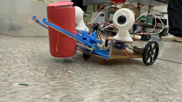
Rover front, with his claw around a red can

Project Overview

For my ENGR 7B course at UCI, I used Solidworks CAD to design, and C++/Arduino to program and operate an autonomous rover capable of line-following, visual object tracking, and picking up an empty soda can. The following design requirements were posed:

  • Must be able to drive autonomously using only the onboard Arduino Uno controler and sensors.
  • Must be able to follow a black line on a white background, on the ground autonomously.
  • Must be able to drive towards a clearly marked red soda can using an onboard camera.
  • Must be able to lift an empty aluminum soda can off the ground
  • Competition performance is measured as the time taken to autonomously complete the course.
  • Sensors are limited to: Pixicam, infrared light sensors

Design Overview

Drivetrain

My drivetrain includes two independently driven drive wheels at the rear and a single caster ball in front. Steering is accomplished by rotating the wheel on one side faster than the wheel on the other side (differential steering). This design allows for turning in place, which is important for the line-detection and following capabilites. Importantly, the infrared line-detection sensors are located near the front of the rover, such that they are far in front of the turning center, allowing for a sweeping motion to find the line.

The Claw

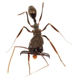
A trap-jaw ant.
A trap-jaw ant. From: "Multifunctionality and mechanical origins: Ballistic jaw propulsion in trap-jaw ants"[Figure 1] by B. Fisher, 2006.
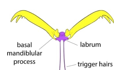
Diagram of the trap-jaw ant pinching mechanism. There are two large pinchers with a trigger in between, jamming them open. There is an indent in the pinchers to allow a small motion of the trigger to free their motion.
Diagram of the trap-jaw ant pinching mechanism. From: "Functional innovation promotes diversification of form in the evolution of an ultrafast trap-jaw mechanism in ants" by D. Booher, 2021.
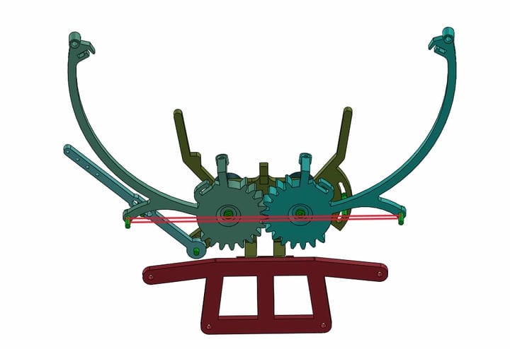
Colored CAD model of the claw in the open position, showing the over-center mechanism and gearing mechanism.
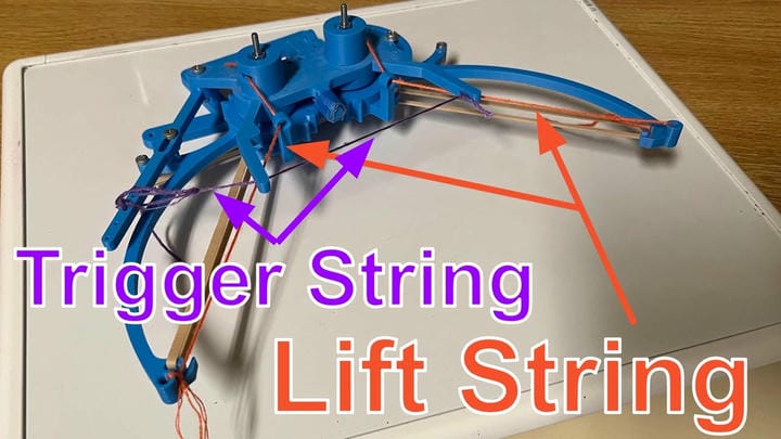
Diagram showing which strings serve which purpose on the claw.
The claw picking up a red soda can slightly above the ground during a test-run.

My claw is the most unique design feature, compared to other rovers in the competition. While most features of my rover are pretty standard (as the provided parts only allow so much freedom), the claw was the one part I wanted to challenge myself with. Although we were provided with small servos to actuate the claw, I was determined to find a solution that would use as few servos as possible. To this end, I settled on a design inspired by the trap-jaw ant (Odontomachus) which utilized zero electrical actuation or sensing.

The mechanical principle behind the claw mechanism is quite simple: using an over-center mechanism, a large amount of mechanical energy can be stored in a system and quickly released when pushed just beyond center. To implement this, I used a rubber band stretched across the entire width of the open claw, such that in the open state the rubber band formed a line just behind the pivot points of the claw arms. Adjustable hard-stops for the claw opening were created to allow for easier adjustment of the mechansim sensitivity without re-printing the components.

By creating an additional arm, positioned with a pivot point behind the claw arm pivot points, I was able to create a trigger. This lever allows a force applied on the inside of the claw to pull the arms just enough to move the rubber band past the center. Then, the claw can close freely under the tension of the rubber band. This force comes from a trigger string specifically placed to activate when the target can is rammed into.

Design Outcome

This design overcomes one of the greatest challenges of foregoing electronic sensing and actuation. Because the aluminum can does not have a lot of friction with the ground, and is very light weight, it was actually very difficult to make a mechanism that was sensitive enough to be triggered by the can, but not too sensitive that it trigger prematurely while navigating the course. The many adjustable dimensions of the design allowed for a lot of experimentation to find the perfect set of geometries that allowed for this goldilocks zone of sensitivity, while still working around the internal friction and lack of mechanical rigidity in the system.

The claw worked very well for the needs of the competition, and actually worked more reliably than some claws using servos. Many teams discovered that the provided servos lacked sufficient torque to effectively lift the can, a problem which I did not have to deal with. It is worth noting that while my claw mechanism could technically lift the can off the ground, limitations in the overall design and rapid closing of the claw when triggered meant that the can was usually only lifted a few millimeters off the ground (which does still qualify for the competition!).

Line-Following Capabilities

I opted to use a 3-sensor line following system, where one sensor is placed in the middle of the width of the chassis, and two more sit to its sides. The programming is very simple for this design, as there are relatively few states the system can be in. If the middle sensor is over the line (but not the other two), then the rover can move straight. If one of the side sensors goes over the line, turn in that direction. Although this is very simple in theory, I discovered that it was very sensitive to vehicle speed, line thickness and contrast (in the infrared spectrum), and sensor update frequency.

Update Frequency Issues

When I tested the rover before the final competition, it did very well, even on the final track. It successfully navigated the course multiple times, with very few failures. In a rather stupid and unjustified move, I determined that I could improve the vehicle's performance by increasing the program's update frequency - a move that would prevent the rover from scoring any points on the official board.

My program was set up to update its sensors and navigation, then wait until a specified time had elapsed since the start of the update. Then, it would update again, giving me control over a consistent update frequency. When I originally tested the rover, i suspect that the update frequency was lower (maybe 100-200Hz), and the rover worked perfectly. I then decided to change that to around 300-400Hz as I was adjusting other code parameters. After this change, the rover failed to correctly detect a specific, very sharp turn on the track. It would frequently end up doing a complete 180 degree turn, ruining its chances of completing the course. Although I only realized this as the likely cause of its failure after the competition was over, I currently think it is the most likely reason.

This failure is a reminder of two things: Version history is important (I did not use any at the time), and; if it ain't broke, don't fix it.

I currently use git for most of my programming projects to allow for easier version management and collaboration with others. I have had multiple occasions where a new "feature" ended up breaking major parts of a program, but with git reverting the change is very simple.
Final Competition

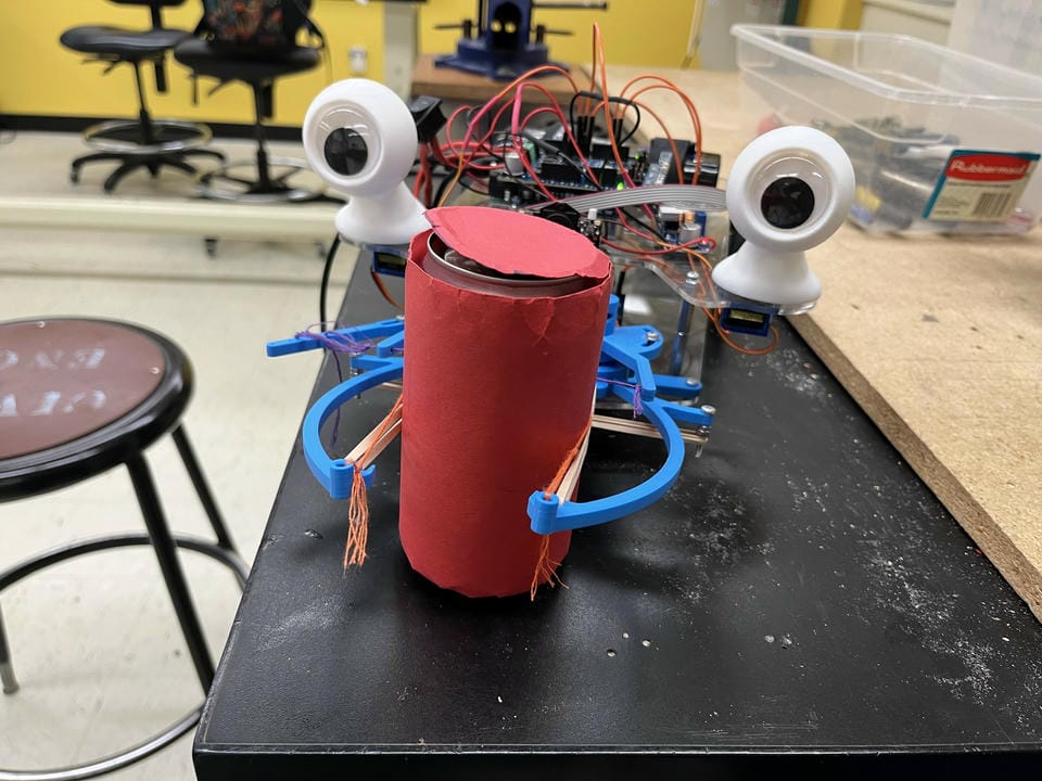
For the final competition, a new track was set up which had never been tested on previously, in a new room. This posed a few challenges to work out in the limited testing time immediately before the competition. Because of differences in lighting and track material, the infrared sensors for line-following needed to be re-calibrated. Although they behaved similarly, I found that they were less reliable in the new environment. This meant that the minimum distance between the sensor and the line was not the same as during previous testing. This negatively impacted the line-following consistancy and led to occasionally not seeing a line and overshooting a turn.

Although I was able to get the robot to complete the course reliably before the competition, I was still tweaking code parameters with the hope of improving the time to complete the course. As discussed in more detail in the line following section, this last-minute tweaking of the code ultimately prevented the robot from earning even a single score on the official leaderboard. This experience was very frustrating at the time, but it is worth noting that of the 10 teams that made it to the final competition, only about half of them managed to get an official time over multiple attempts.

Despite its failures during the competition, I am very proud of the end result - a culmination of months of my own effort to design, prototype, manufacture, and program a unique system that managed to perform better than many other teams.